LightAct 4.7 includes integration with UE5.4, an improved Curve editing workflow, a lot of new and updated nodes, new DMX-related features as well as a brand new OptiTrack integration, allowing you to achieve fast Projector Calibration using Prime cameras.
Unreal Engine 5.4
- Unreal Engine 5.4 is compatible with LightAct 4.7.0. To find out how to set the integration up, you can follow this tutorial.
- To get the texture from Unreal Engine with LightAct Cameras and LiveLink you can follow this tutorial.
- You can get the texture from Unreal Engine through Ndisplay following this tutorial.
General
-
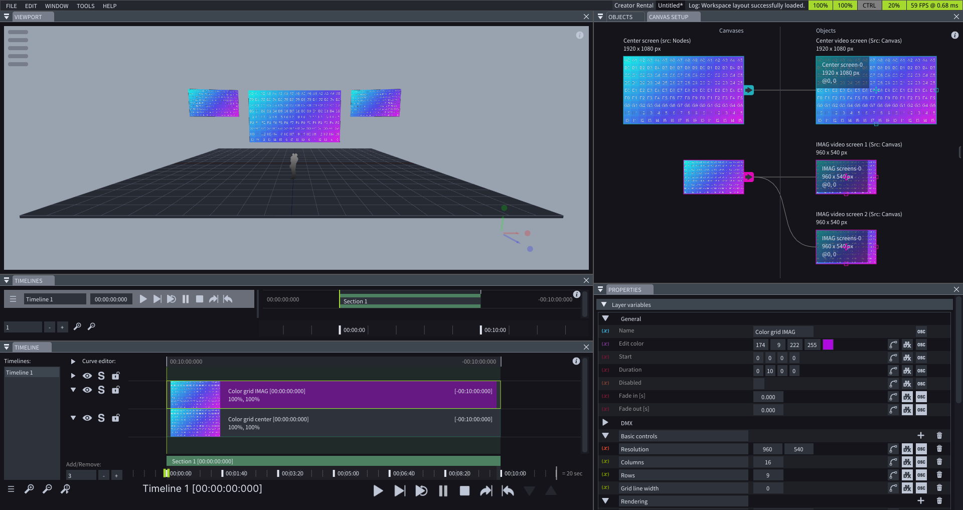
When you open LightAct, it displays a Start project that showcases the basic content mapping workflow.
-
In the Quick tips of each window, you can find the shortcuts that apply to that window.
-
You can now save the desired location of the Viewport Camera and restore this location. The stored locations can be found in the Viewport’s menu.
Curve Editor
-
Curve editing is now done in the Timeline window under the Curve editor section. To edit a Variable’s curve, enable its Curve editing button and select both the Layer and the Variable to visualize the curve.
-
The Create keyframe option adds a new Curve point to each curve visible in the Curve editor at the Playhead’s position.
-
Scrolling on a selected Curve point changes its value. Shift + scroll moves the selected Curve point along the Timeline.
-
To display the values of all selected Curve points and the Curve points at the Playhead’s position, enable the Show curve values checkbox in the menu at the bottom left of the Timeline window.
-
The Move keyframes with layer checkbox, which can be found in the menu on the bottom left of the Timeline window, ensures Curve editor points move with the Layer when it’s repositioned on the Timeline. If unchecked, the Curve editor points stay at their original Timeline positions regardless of the Layer’s movement.

Timelines
-
Under the name of each Timeline, you can find the Update time of the whole Timeline.
-
To create a new Timeline or delete the current Timeline from the Timeline window, click the menu on the bottom left side and choose Create new or Delete current respectively.
Layer connections
-
Layer connections window allows you to pass variables between Layers. If a Layer connection is active, the Source variables will control the chosen Destination variables.
-
Dragging from a Variable to another Layer lets you form a Layer connection between your Source variable and all the Variables of the same type in the Destination Layer.
Nodes
-
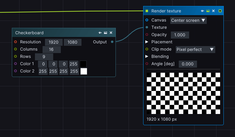
Right-clicking on a Thumbnail lets you export the texture that the Node is generating.
-
Right-clicking on the Header of a node lets you access the node’s right-click menu which includes the Bypass, Preview, and Delete options.
-
The checkerboard texture node generates a checkerboard texture.
-
You can modify the position, rotation, and scale of a Viewport object with the Set transform data node.
-
Instead of just displaying the Size of the array, Append nodes now display the exact data they are fed.
-
You can convert Vec2 data to Resolution data by using the Vec2 to Resolution Convert node.
-
You can send PSN tracking data using a specific TrackID.
-
Write to file node populates the chosen file with the contents added to the Input pin of the node.
-
Read from file node outputs the contents of a chosen file.
-
You can change the state of a Timeline by using the Set data node called Timeline state.
-
The Run autoblend node simulates the action of clicking on the Blend button in the Autoblend window.
-
Simple value nodes are renamed to Generate value nodes.
-
New node search keywords.

DMX
-
The Fixture Placement feature allows you to automatically place a Fixture on the Viewport based on a .csv file.
-
All numerical Variables now have a Remap DMX value to min max range option. If enabled, the incoming DMX value is scaled to fit within the specified Min and Max range.
-
DMX by UV node has been upgraded with an Advanced section. Channel offset determines how many Channels each address of an individual pixel shifts. If the incoming texture has a different resolution than the CSV resolution, you can use the Adapt resolution checkbox.
OptiTrack
-
New Prime camera receiver node, capable of receiving Prime camera feed and detecting Passive and Active Markers.
-
You can choose Prime cameras as a source of Iris viewport objects.
-
You can calibrate a Prime camera using OptiTrack’s Active or Passive Markers as Projected points, instead of manually selecting Projected points in the 3D Cal window.
-
New Set data node called Prime camera params that allows you to change the parameters of the Prime camera receiver device node.
3D Cal
-
If Show projected point popup checkbox is enabled, the view of the selected Virtual point from the Projected space will appear in a pop-up window.
-
To toggle the visibility of the Labels in the 3D Cal window you can either press L key or use the Show labels checkbox.
-
New Calibrate Iris camera node that simulates the action of clicking on the Calibrate button in the 3D Cal window of the Iris camera viewport object.

IRIS
-
You can now manually choose the Calibration points that will be considered during IRIS calibration.
-
Expert mode in IRIS Window allows you to choose which Cameras will be responsible for calibrating which Projectors.
-
You can decide exactly how many Empty projector and Empty camera frames should be included during IRIS Calibration, so the setup is tailored to your hardware. This will directly affect the time needed for the IRIS Calibration to complete.
-
More extensive Logs are included during IRIS calibration.
Other
-
Hovering over a Collection in the Objects window will tell you exactly how many children the Collection has.
-
Projectors use another Antialiasing technique, which allows you to choose the number of Samples, the Distribution, and the Filter.
-
You can change the Near clip and Far clip of a Projector under the Frustum properties in the Properties window.
-
Enable the Generate depth images checkbox in the Autoblend window to generate a Depth image from the Projector view. You can then visualize it in the Depth image node in the Projector’s setup window.
-
Canvases, Timelines, Sections, and Markers, have a Notes section which can be found at the bottom of the Properties window.