Hi there! Firstly, we love LightAct But we are experiencing a serious problem that we hope to resolve urgently, in time for our next project.
We noticed that there is a mismatch between the dimensions of the projected image calculated in LightAct vs the real-life dimensions we measure on site. This means that we cannot be sure of LightAct’s simulations, and we cannot accurately pre-visualize and model our setups. We did the control test below because we encountered a problem on a big project and ran into issues on site because the throw ratios simulated in LightAct seem to have been inaccurate, and consequently the lenses we sourced could not cover the desired area on site.
Latest control test:
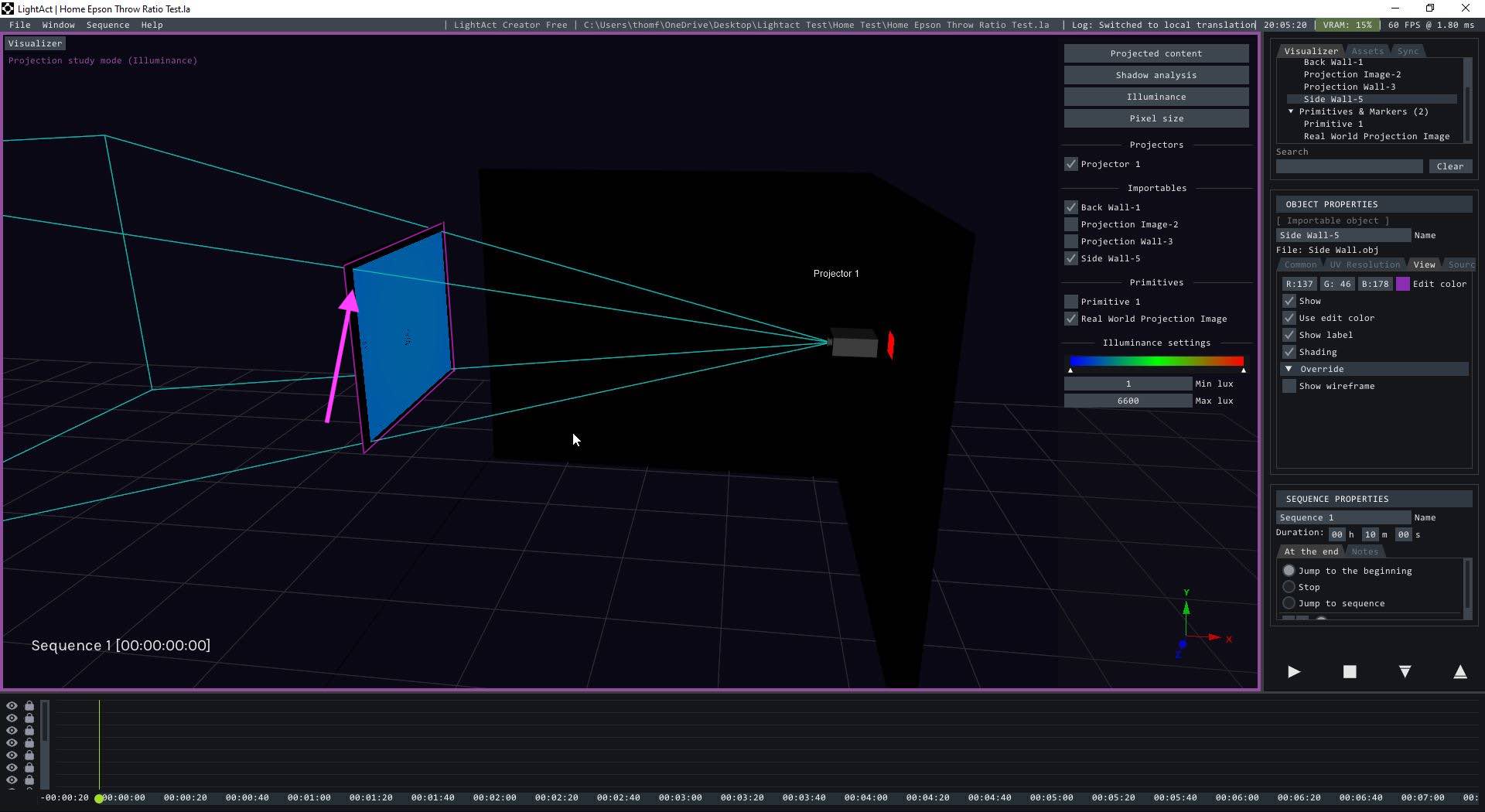
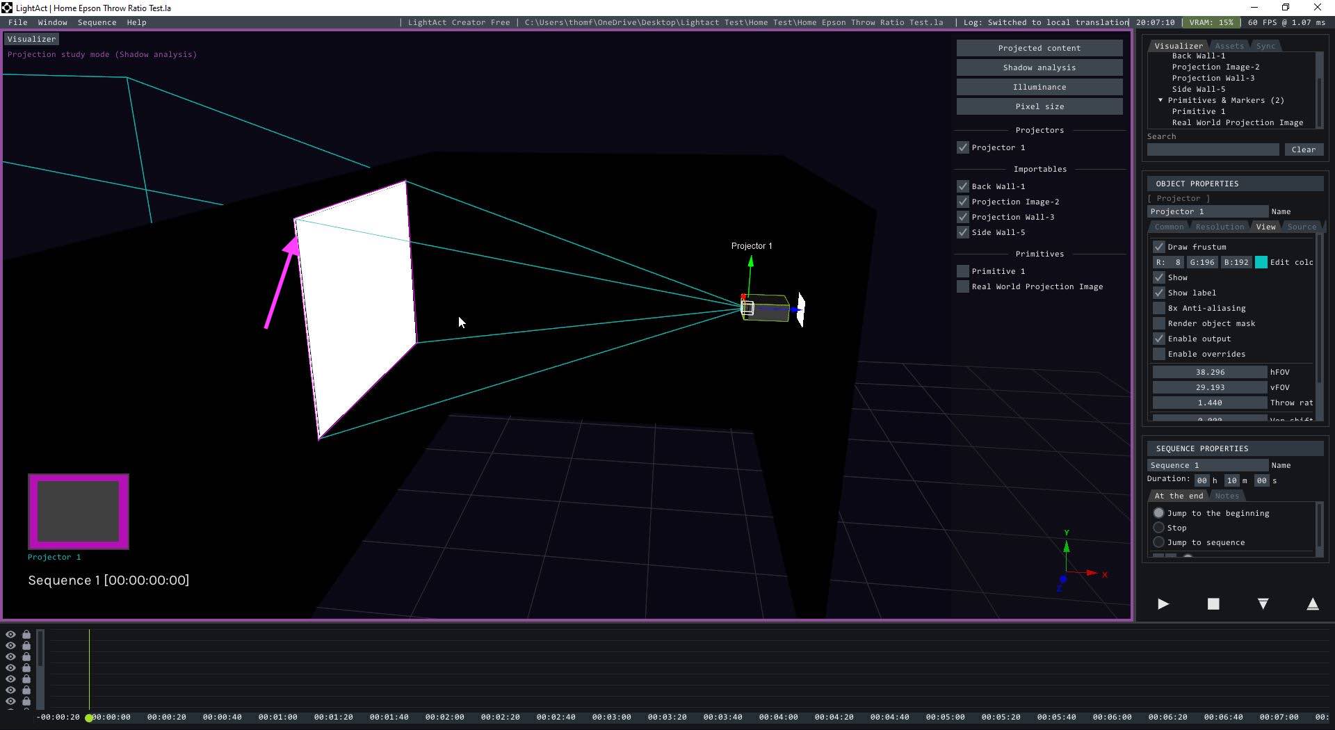
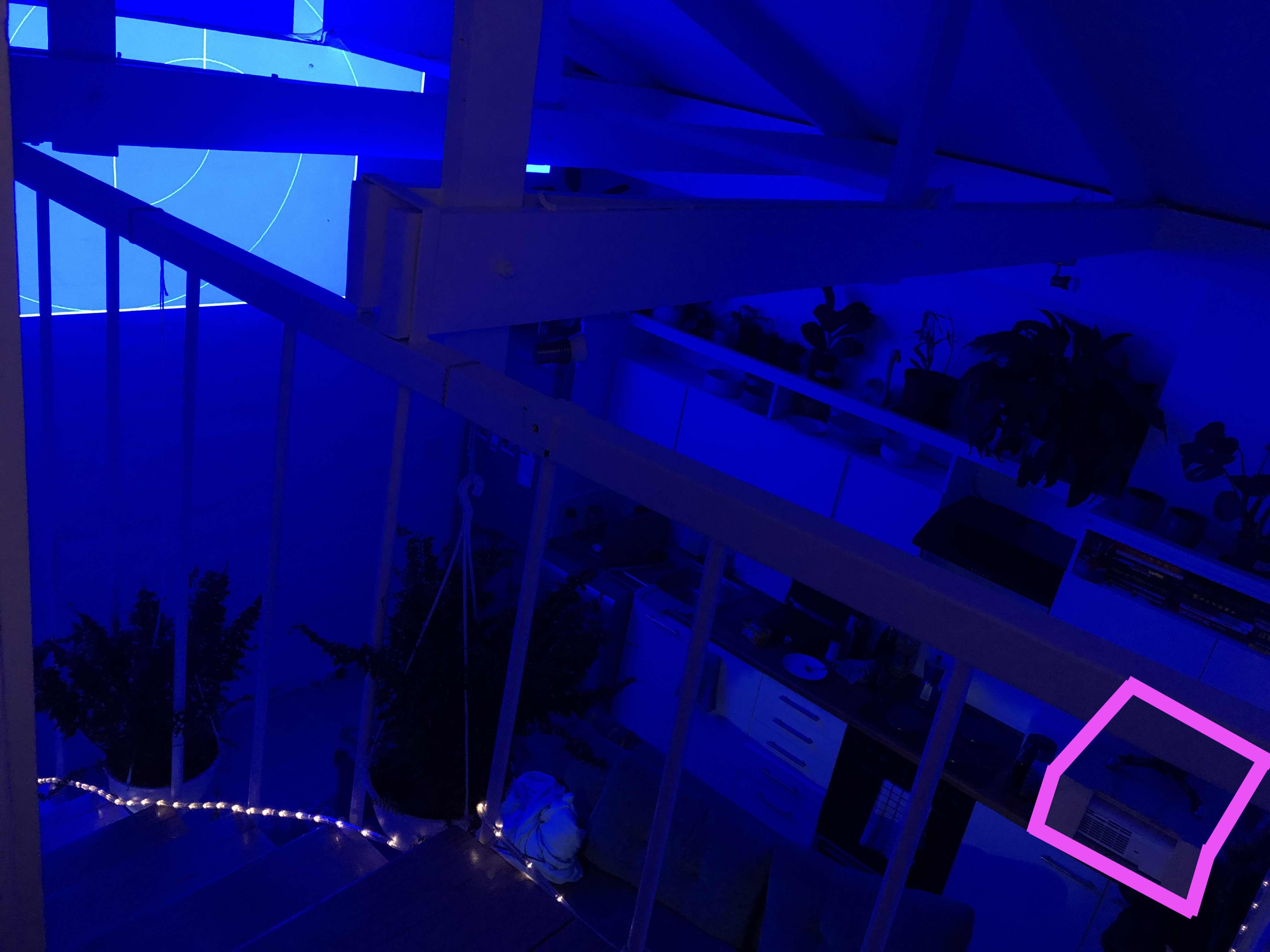
Projector: EPSON EB-E01, 4:3 aspect ratio, 1024x768, 3300lumen. We set up a real projector in a room, and recreated the room and projector setup in LightAct. We then compared the size of the physical projected image against the size of the projected image in the LightAct simulation. To do this we measured both the minimum and maximum projected images permitted by the throw ratio (1.44 and 1.95, as per the projector’s spec sheet) and compared with the simulation. In order to achieve the same projected image size in LightAct, we had to push the throw ratio to 1.49 and 1.74 respectively, to match the real-world projected image sizes.
We normally use Panasonic PTDZ21K projectors, and have an upcoming project in which we need to use x8 of these together. While the discrepancy may seem very small in the control test, this mismatch translates to big discrepancies on bigger surfaces. We would really love to use LightAct to plan the exact placement of the projectors. Any ideas on how to fix the mismatch would be deeply appreciated!
It’s always possible that a bug has crept into our software, so in order to double-check this functionality, I created this little project with 2 projectors:
Before we begin, let’s remind ourselves again of the throw ratio’s formula. It is defined as throwRatio = d/w where:
d = distance between the projector and the image plane
w = width of the image
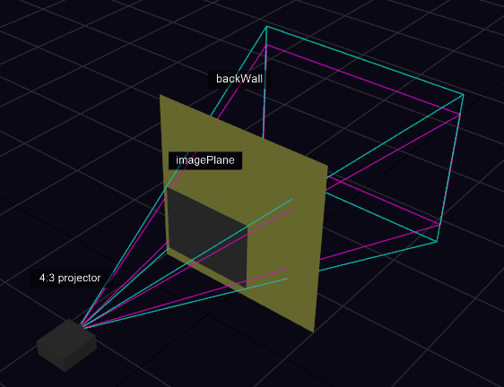
So in the project, you’ll see 2 planes:
one depicting the projector’s image (imagePlane). Due to the above formula, we are actually interested only in width, which I set to 100 cm.
the second (backWall) serves as a helper so that we can clearly see when the projector’s image extends beyond the imagePlane plane.
If you switch to Projection study in Shadow Analysis mode and move the projector backwards and forwards, the idea is to place the projector just so that there are no projected pixels on the back wall, yet that the entire width of the imagePlane is lit.
If I use a projector with:
throwRatio = 1.7, I have to place it at 170cm. Since image plane is 100cm, it means 170/100=1.7
throwRatio = 2.6, I have to place it at 260cm. Since image plane is 100cm, it means 260/100=2.6
So, I believe the calculation is correct, isn’t it? It is possible I misunderstood something in which case, please feel free to let me know.
We follow your math, and agree that within LightAct it seems to make sense.
But just to make sure we understand your reasoning correctly — did you also do a physical test and compared it with the LightAct simulation?
We suspect that there might be real-world inconsistencies or deviations in throw ratio between different projector brands. Have you experienced this before?